

A while ago, we discussed the cross-site replication feature of the Percona PXC operator. Recently, a similar cross-site replication feature was introduced in the Percona (PS MySQL) operator v1.2.0, a topology based on Group Replication/InnoDB Cluster.
In this blog post, we will explore how to add a DR Cluster to an existing DC Cluster to form a ClusterSet environment, which provides a seamless switchover between DC/DR members. The good part is that all the complexity and configuration will be managed by the Percona operator, with very few setup steps required.
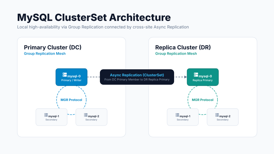
Let’s discuss how we can implement a cross-site replication (DC-DR) topology across two separate database clusters.
Step 1: Deploying the cluster on the DC side.
|
1 2 3 |
shell> kubectl get ps -n ps NAME REPLICATION ENDPOINT STATE MYSQL ORCHESTRATOR HAPROXY ROUTER AGE ps-cluster1 group-replication ps-cluster1-haproxy.ps ready 3 3 28m |
|
1 2 3 4 5 6 7 8 9 |
shell> kubectl get pods -n ps NAME READY STATUS RESTARTS AGE percona-server-mysql-operator-6b78d5f68c-bzg6r 1/1 Running 0 30m ps-cluster1-haproxy-0 2/2 Running 0 28m ps-cluster1-haproxy-1 2/2 Running 0 27m ps-cluster1-haproxy-2 2/2 Running 0 27m ps-cluster1-mysql-0 2/2 Running 0 29m ps-cluster1-mysql-1 2/2 Running 0 28m ps-cluster1-mysql-2 2/2 Running 0 26m |
Step 2: Retrieve the DC’s InnoDB cluster name, which will be required later to construct the ClusterSet.
|
1 2 |
shell> kubectl get ps ps-cluster1 -n ps -o jsonpath='{.status.innodbClusterName}{"\n"}' pscluster1 |
Step 3: Get a service endpoint which is used when setting up the ClusterSet environment. We will use ps-cluster1-mysql-primary, which is mapped to the current Primary node in the existing cluster.
|
1 2 3 4 5 6 7 8 |
shell> kubectl get services -n ps NAME TYPE CLUSTER-IP EXTERNAL-IP PORT(S) AGE ps-cluster1-haproxy ClusterIP 34.118.225.215 <none> 3306/TCP,3307/TCP,3309/TCP,33060/TCP,33062/TCP 29m ps-cluster1-mysql ClusterIP None <none> 3306/TCP,33062/TCP,33060/TCP,6450/TCP,33061/TCP 29m ps-cluster1-mysql-primary ClusterIP 34.118.229.137 <none> 3306/TCP,33062/TCP,33060/TCP,6450/TCP,33061/TCP 29m ps-cluster1-mysql-proxy ClusterIP None <none> 3306/TCP,33062/TCP,33060/TCP,6450/TCP,33061/TCP 29m ps-cluster1-mysql-unready ClusterIP None <none> 3306/TCP,33062/TCP,33060/TCP,6450/TCP,33061/TCP 29m |
Step 4: The DR site should have the same credentials as DC. We need to export the DC secret containing the credentials and import it into the DR cluster.
|
1 |
shell> kubectl get secret ps-cluster1-secrets -n ps -o yaml > source-secret.yaml |
We also need to perform a couple of cleanups in the exported secret file.
E.g,
|
1 |
shell> yq eval 'del(.metadata.ownerReferences, .metadata.annotations, .metadata.creationTimestamp, .metadata.resourceVersion, .metadata.selfLink, .metadata.uid)' source-secret.yaml > replica-secret.yaml |
|
1 |
shell> yq eval '.metadata.namespace = "ps-dr"' -i replica-secret.yaml |
|
1 |
shell> sed -i '' 's/ps-cluster1/ps-cluster2/g' replica-secret.yaml |
The final ready secret file looks like this.
|
1 2 3 4 5 6 7 8 9 10 11 12 13 14 15 16 17 18 19 20 21 |
apiVersion: v1 data: clusterset: XVpMQz0+LEVDe3kyQGR6TQ== heartbeat: YmFONW1KTE8oLTxdVVB7Kg== monitor: UC1oOHokRksoMnpSMWsmJg== operator: SDMrblpSQm0yRHdhV3dteX0= orchestrator: cEVqMEUlaGp5fShudyZURHtl replication: ZjldZlkwa3ZwNWU8KVpsag== root: e3BycEl+LlcrPFVUUTwpaG4= xtrabackup: eFhNNENIRF4wJXZ7bjxbKi11ag== kind: Secret metadata: labels: app.kubernetes.io/component: database app.kubernetes.io/instance: ps-cluster2 app.kubernetes.io/managed-by: percona-server-mysql-operator app.kubernetes.io/name: mysql app.kubernetes.io/part-of: percona-server name: ps-cluster2-secrets namespace: ps-dr type: Opaque |
Step 1: First, we need to import the modified secret file replica-secret.yaml and initialise the DR cluster.
|
1 2 |
shell> kubectl apply -f deploy/replica-secret.yaml -n ps-dr secret/ps-cluster2-secrets created |
|
1 2 3 4 5 |
shell> kubectl get secrets -n ps-dr NAME TYPE DATA AGE ... ps-cluster2-secrets Opaque 8 12s ... |
Also, we need to make some modifications to the custom resource file cr.yaml to initialise the DR cluster.
|
1 2 3 4 5 6 7 8 9 10 |
metadata: finalizers: - percona.com/delete-mysql-pods-in-order # - percona.com/delete-ssl # - percona.com/delete-mysql-pvc name: ps-cluster2 spec: crVersion: 1.2.0 secretsName: ps-cluster2-secrets |
|
1 2 3 4 5 6 |
mysql: clusterType: group-replication size: 3 image: percona/percona-server:8.4.10-10.1 bootstrap: mode: manual |
|
1 |
shell> kubectl apply -f deploy/cr.yaml -n ps |
Note: We set spec.mysql.bootstrap.mode to manual so Pod mysql-0 does not form a Group Replication group until the ClusterSet adopts it and references the secret file we copied from the DC.
It is also expected that after applying the Custom Resource file cr.yaml, the Pod mysql-0 starts but stays NotReady. The cluster ps-cluster2 reports the Initialising state and the AwaitingExternalBootstrap condition in status. Pods mysql-1 and mysql-2 do not start until Pod mysql-0 joins the Group Replication.
Once we deploy the custom resource, we can notice the status below. Please note that the complete Pods will be ready only once DR successfully syncs and joins the DC cluster.
|
1 2 3 |
shell> kubectl get ps -n ps-dr NAME REPLICATION ENDPOINT STATE MYSQL ORCHESTRATOR HAPROXY ROUTER AGE ps-cluster2 group-replication ps-cluster2-haproxy.ps-dr initializing 17m |
|
1 2 3 4 |
shell> kubectl get pods -n ps-dr NAME READY STATUS RESTARTS AGE percona-server-mysql-operator-6b78d5f68c-4gsm9 1/1 Running 0 28m ps-cluster2-mysql-0 |
Step 2: We need to note down the DR InnoDB cluster name, which will later be used by the ClusterSet.
|
1 2 |
shell> kubectl get ps ps-cluster2 -n ps -o jsonpath='{.status.innodbClusterName}{"\n"}' pscluster2 |
Step 3: We need to identify the DR cluster endpoint that is reachable from the DC. This endpoint will be used to feed the clone and perform other management operations.
We will use the local FQDN ps-cluster2-mysql-0.ps-cluster2-mysql.ps-dr.svc.cluster.local of the ps-cluster2-mysql-0 Pod, which is currently initialised and awaiting the ready state.
|
1 2 3 4 |
shell> kubectl get pods -n ps-dr NAME READY STATUS RESTARTS AGE percona-server-mysql-operator-6b78d5f68c-4gsm9 1/1 Running 0 48m ps-cluster2-mysql-0 1/2 Running 0 37m |
By connecting to the DC Primary Pod, we can verify cross-communication between the DC and the DR.
|
1 |
shell> kubectl exec -it ps-cluster1-mysql-0 -n ps -- sh |
|
1 2 3 4 5 6 7 |
sh-5.1$ curl -v ps-cluster2-mysql-0.ps-cluster2-mysql.ps-dr.svc.cluster.local:3306 * Trying 10.60.1.7:3306... * Connected to ps-cluster2-mysql-0.ps-cluster2-mysql.ps-dr.svc.cluster.local (10.60.1.7) port 3306 (#0) > GET / HTTP/1.1 > Host: ps-cluster2-mysql-0.ps-cluster2-mysql.ps-dr.svc.cluster.local:3306 > User-Agent: curl/7.76.1 > Accept: */* |
By default, when the DR site initialises and attempts to join the ClusterSet, it receives data from the source/DC via the clone recovery method.
The Operator uses MySQL Shell to create a physical snapshot of the dataset from the Source/DC and transfer it to the DR Replica.
Alternatively, we can manually perform a backup and restore on the target cluster. This strategy helps when integrating the DR site into the ClusterSet, as pre-populating the data and GTID history allows it to apply only delta changes rather than performing a full initial synchronisation. For large datasets or to prevent excessive load and performance degradation on the donor node, a backup-and-restore approach can be considered.
Here, we will use the clone recovery method to sync the DR cluster.
Next, we will deploy the ClusterSet configurations so that DR joins the DC cluster via a data clone and connects via Asynchronous Replication to stay in sync.
Below is the clusterset.yaml file where we pass the various information like (Secrets, DC/DR Endpoints, Cluster Name etc) , which we fetched in some of the above steps earlier.
|
1 2 3 4 5 6 7 8 9 10 11 12 13 14 15 16 17 18 19 20 21 22 23 24 25 26 27 |
kind: PerconaServerMySQLClusterSet metadata: name: my-cluster-set finalizers: - percona.com/clusterset-dissolve spec: # unsafeFlags: # forcedFailover: false # forcedClusterRemoval: false primaryCluster: pscluster1 credentialsSecret: name: ps-cluster1-secrets key: clusterset sslMode: AUTO createReplicaClusterOptions: recoveryMethod: clone clusters: - innodbClusterName: pscluster1 endpoints: - host: ps-cluster1-mysql-primary.ps.svc.cluster.local port: 3306 - innodbClusterName: pscluster2 endpoints: - host: ps-cluster2-mysql-0.ps-cluster2-mysql.ps-dr.svc.cluster.local port: 3306 mysqlshellRunner: image: percona/percona-server:8.4.10-10.1 |
We will apply the changes only to the DC node.
|
1 |
kubectl apply -f deploy/clusterset.yaml |
Please note: Member “ps-cluster2-mysql-0” on the DR side will connect to the DC via asynchronous replication. While the local members of the DR will join via the Group Replication mechanism.
This action will also start a separate backend job on DC, which creates an associated Pod to perform the ClusterSet activity.
|
1 2 3 |
shell> kubectl get jobs -n ps NAME STATUS COMPLETIONS DURATION AGE my-cluster-set-pscluster2-add-replica Complete 1/1 23s 53s |
….
|
1 2 3 |
shell> kubectl get pods -n ps NAME READY STATUS RESTARTS AGE my-cluster-set-pscluster2-add-replica-wk7xd 1/1 Running 0 3s |
As soon as the process completes successfully, the job and associated Pod will be removed from the list.
There is one extra pod that can be noticed, and it persists. This provides a utility/client for running MySQL Shell commands against the MySQL ClusterSet.
|
1 2 3 |
shell> kubectl get pods -n ps NAME READY STATUS RESTARTS AGE my-cluster-set-runner-5d68fbcc74-svmpw 1/1 Running 0 10h |
If the job fails or errors occur, we need to investigate the exact problem using the information below.
|
1 2 3 |
kubectl describe job <jobname> kubectl describe pod <add-replica pod> kubectl logs <add-replica pod> |
Finally, we can check the Pod status on the DR cluster. It will now reflect all MySQL and haproxy pods in the fully completed/ready state.
|
1 2 3 4 5 6 7 8 9 |
shell> kubectl get pods -n ps-dr NAME READY STATUS RESTARTS AGE percona-server-mysql-operator-6b78d5f68c-4gsm9 1/1 Running 0 11h ps-cluster2-haproxy-0 2/2 Running 0 36m ps-cluster2-haproxy-1 2/2 Running 0 36m ps-cluster2-haproxy-2 2/2 Running 0 36m ps-cluster2-mysql-0 2/2 Running 1 (37m ago) 11h ps-cluster2-mysql-1 2/2 Running 1 (36m ago) 36m ps-cluster2-mysql-2 2/2 Running 1 (34m ago) 35m |
We can check the ClusterSet information below if it has been processed successfully without any errors.
|
1 2 3 |
shell> kubectl get ps-clusterset my-cluster-set -n ps NAME PRIMARY ENDPOINT READY my-cluster-set pscluster1 ps-cluster1-mysql-0.ps-cluster1-mysql.ps:3306 True |
|
1 2 3 4 5 6 7 8 9 10 11 12 13 14 15 16 17 18 19 20 21 22 23 24 25 26 27 28 29 30 31 32 33 34 35 36 37 38 39 40 41 42 43 44 45 46 47 48 49 50 51 52 53 54 55 56 57 58 59 60 61 62 63 64 |
shell> kubectl get ps-clusterset my-cluster-set -n ps -o yaml apiVersion: ps.percona.com/v1 kind: PerconaServerMySQLClusterSet metadata: annotations: kubectl.kubernetes.io/last-applied-configuration: | {"apiVersion":"ps.percona.com/v1","kind":"PerconaServerMySQLClusterSet","metadata":{"annotations":{},"finalizers":["percona.com/clusterset-dissolve"],"name":"my-cluster-set","namespace":"ps"},"spec":{"clusters":[{"endpoints":[{"host":"ps-cluster1-mysql-primary.ps.svc.cluster.local","port":3306}],"innodbClusterName":"pscluster1"},{"endpoints":[{"host":"ps-cluster2-mysql-0.ps-cluster2-mysql.ps-dr.svc.cluster.local","port":3306}],"innodbClusterName":"pscluster2"}],"createReplicaClusterOptions":{"recoveryMethod":"clone"},"credentialsSecret":{"key":"clusterset","name":"ps-cluster1-secrets"},"mysqlshellRunner":{"image":"percona/percona-server:8.4.10-10.1"},"primaryCluster":"pscluster1","sslMode":"AUTO"}} creationTimestamp: "2026-09-11T05:20:08Z" finalizers: - percona.com/clusterset-dissolve generation: 5 name: my-cluster-set namespace: ps resourceVersion: "1789143099049519007" uid: 6cfdce40-e1e0-47c8-bdae-1cd847938f29 spec: clusters: - endpoints: - host: ps-cluster1-mysql-primary.ps.svc.cluster.local port: 3306 innodbClusterName: pscluster1 - endpoints: - host: ps-cluster2-mysql-0.ps-cluster2-mysql.ps-dr.svc.cluster.local port: 3306 innodbClusterName: pscluster2 createReplicaClusterOptions: recoveryMethod: clone credentialsSecret: key: clusterset name: ps-cluster1-secrets mysqlshellRunner: image: percona/percona-server:8.4.10-10.1 primaryCluster: pscluster1 sslMode: AUTO status: clusters: pscluster1: clusterRole: PRIMARY globalStatus: OK primary: ps-cluster1-mysql-0.ps-cluster1-mysql.ps:3306 pscluster2: clusterRole: REPLICA globalStatus: OK primary: "" conditions: - lastTransitionTime: "2026-09-11T05:25:07Z" message: "" reason: DeploymentReady status: "True" type: MySQLShellRunnerReady - lastTransitionTime: "2026-09-11T05:25:10Z" message: "" reason: ClusterSetBootstrapped status: "True" type: ClusterSetBootstrapped - lastTransitionTime: "2026-09-11T05:25:13Z" message: All Clusters available. reason: ClusterSetHealthy status: "True" type: Ready lastObservedAt: "2026-09-11T16:11:39Z" lastObservedGeneration: 5 primaryCluster: pscluster1 primaryClusterEndpoint: ps-cluster1-mysql-0.ps-cluster1-mysql.ps:3306 |
Also, we can manually access any running MySQL Pod and confirm the ClusterSet status.
|
1 |
shell> kubectl exec -it ps-cluster1-mysql-0 -n ps -- sh |
|
1 |
sh-5.1$ mysqlsh --uri=root@localhost:3306 |
|
1 2 3 4 5 6 7 8 9 10 11 12 13 14 15 16 17 18 19 20 21 22 23 24 25 26 27 28 29 30 31 32 33 34 35 36 37 38 39 40 41 42 43 44 45 46 47 48 49 50 51 52 53 54 55 56 57 58 59 60 61 62 63 64 65 66 67 68 69 70 71 72 73 74 75 76 77 78 79 80 81 82 83 84 85 86 87 88 89 90 91 92 93 94 95 96 97 98 99 100 101 102 103 104 105 106 107 108 109 110 |
MySQL localhost:3306 ssl JS > var clusterset = dba.getClusterSet() MySQL localhost:3306 ssl JS > clusterset.status({extended:1}) { "clusters": { "pscluster1": { "clusterRole": "PRIMARY", "globalStatus": "OK", "primary": "ps-cluster1-mysql-0.ps-cluster1-mysql.ps:3306", "status": "OK", "statusText": "Cluster is ONLINE and can tolerate up to ONE failure.", "topology": { "ps-cluster1-mysql-0.ps-cluster1-mysql.ps:3306": { "address": "ps-cluster1-mysql-0.ps-cluster1-mysql.ps:3306", "memberRole": "PRIMARY", "mode": "R/W", "readReplicas": {}, "role": "HA", "status": "ONLINE", "version": "8.4.10" }, "ps-cluster1-mysql-1.ps-cluster1-mysql.ps:3306": { "address": "ps-cluster1-mysql-1.ps-cluster1-mysql.ps:3306", "memberRole": "SECONDARY", "mode": "R/O", "readReplicas": {}, "replicationLagFromImmediateSource": "", "replicationLagFromOriginalSource": "", "role": "HA", "status": "ONLINE", "version": "8.4.10" }, "ps-cluster1-mysql-2.ps-cluster1-mysql.ps:3306": { "address": "ps-cluster1-mysql-2.ps-cluster1-mysql.ps:3306", "memberRole": "SECONDARY", "mode": "R/O", "readReplicas": {}, "replicationLagFromImmediateSource": "", "replicationLagFromOriginalSource": "", "role": "HA", "status": "ONLINE", "version": "8.4.10" } }, "transactionSet": "50cc4081-ad9a-11f1-b815-1602eb3926cb:1-4,65edbac6-ad9a-11f1-9dbe-1602eb3926cb:1-139" }, "pscluster2": { "clusterRole": "REPLICA", "clusterSetReplication": { "applierStatus": "APPLIED_ALL", "applierThreadState": "Waiting for an event from Coordinator", "applierWorkerThreads": 4, "receiver": "ps-cluster2-mysql-0.ps-cluster2-mysql.ps-dr:3306", "receiverStatus": "ON", "receiverThreadState": "Waiting for source to send event", "replicationSsl": "TLS_AES_128_GCM_SHA256 TLSv1.3", "replicationSslMode": "REQUIRED", "source": "ps-cluster1-mysql-0.ps-cluster1-mysql.ps:3306" }, "clusterSetReplicationStatus": "OK", "globalStatus": "OK", "status": "OK", "statusText": "Cluster is ONLINE and can tolerate up to ONE failure.", "topology": { "ps-cluster2-mysql-0.ps-cluster2-mysql.ps-dr:3306": { "address": "ps-cluster2-mysql-0.ps-cluster2-mysql.ps-dr:3306", "memberRole": "PRIMARY", "mode": "R/O", "readReplicas": {}, "replicationLagFromImmediateSource": "", "replicationLagFromOriginalSource": "", "role": "HA", "status": "ONLINE", "version": "8.4.10" }, "ps-cluster2-mysql-1.ps-cluster2-mysql.ps-dr:3306": { "address": "ps-cluster2-mysql-1.ps-cluster2-mysql.ps-dr:3306", "memberRole": "SECONDARY", "mode": "R/O", "readReplicas": {}, "replicationLagFromImmediateSource": "", "replicationLagFromOriginalSource": "", "role": "HA", "status": "ONLINE", "version": "8.4.10" }, "ps-cluster2-mysql-2.ps-cluster2-mysql.ps-dr:3306": { "address": "ps-cluster2-mysql-2.ps-cluster2-mysql.ps-dr:3306", "memberRole": "SECONDARY", "mode": "R/O", "readReplicas": {}, "replicationLagFromImmediateSource": "", "replicationLagFromOriginalSource": "", "role": "HA", "status": "ONLINE", "version": "8.4.10" } }, "transactionSet": "50cc4081-ad9a-11f1-b815-1602eb3926cb:1-4,65edbac6-ad9a-11f1-9dbe-1602eb3926cb:1-139", "transactionSetConsistencyStatus": "OK", "transactionSetErrantGtidSet": "", "transactionSetMissingGtidSet": "" } }, "domainName": "my-cluster-set", "globalPrimaryInstance": "ps-cluster1-mysql-0.ps-cluster1-mysql.ps:3306", "metadataServer": "ps-cluster1-mysql-0.ps-cluster1-mysql.ps:3306", "primaryCluster": "pscluster1", "status": "HEALTHY", "statusText": "All Clusters available." } |
|
1 2 3 4 5 6 |
shell> export PRIMARY=$(kubectl get pods -n ps -l mysql.percona.com/primary=true -o jsonpath='{.items[0].metadata.name}') shell> echo $PRIMARY; ps-cluster1-mysql-0 shell> kubectl exec -it ps-cluster1-mysql-0 -n ps -- sh shell> mysql -uroot -p |
|
1 2 |
mysql> CREATE DATABASE IF NOT EXISTS test; mysql> CREATE TABLE IF NOT EXISTS test.t1 (id INT PRIMARY KEY); INSERT INTO test.t1 VALUES (1); |
|
1 2 |
shell> kubectl exec -it ps-cluster2-mysql-0 -n ps-dr -- sh shell> mysql -uroot -p |
|
1 2 3 4 5 6 |
mysql> SELECT * FROM test.t1; +----+ | id | +----+ | 1 | +----+ |
We can also visit any MySQL Pod and run the following command to get the Primary member and group replication details.
|
1 2 3 4 5 6 7 8 9 |
mysql> select * from performance_schema.replication_group_members; +---------------------------+--------------------------------------+------------------------------------------+-------------+--------------+-------------+----------------+----------------------------+ | CHANNEL_NAME | MEMBER_ID | MEMBER_HOST | MEMBER_PORT | MEMBER_STATE | MEMBER_ROLE | MEMBER_VERSION | MEMBER_COMMUNICATION_STACK | +---------------------------+--------------------------------------+------------------------------------------+-------------+--------------+-------------+----------------+----------------------------+ | group_replication_applier | 50cc4081-ad9a-11f1-b815-1602eb3926cb | ps-cluster1-mysql-0.ps-cluster1-mysql.ps | 3306 | ONLINE | PRIMARY | 8.4.10 | MySQL | | group_replication_applier | 87137873-ad9a-11f1-ae3f-36b4b899b0ff | ps-cluster1-mysql-1.ps-cluster1-mysql.ps | 3306 | ONLINE | SECONDARY | 8.4.10 | MySQL | | group_replication_applier | b952f0d3-ad9a-11f1-95a5-d6e7036e522a | ps-cluster1-mysql-2.ps-cluster1-mysql.ps | 3306 | ONLINE | SECONDARY | 8.4.10 | MySQL | +---------------------------+--------------------------------------+------------------------------------------+-------------+--------------+-------------+----------------+----------------------------+ 3 rows in set (0.00 sec) |
Performing a planned switchover or an ad hoc failover process is quite simple here. All we need to execute the operations below.
Switchover:
|
1 2 |
shell> kubectl patch ps-clusterset my-cluster-set -n $SOURCE_NS \ --type=merge -p '{"spec":{"primaryCluster":"replicacluster"}}' |
Forced Failover:
|
1 2 3 4 5 6 7 8 |
shell> kubectl patch ps-clusterset my-cluster-set -n $SOURCE_NS --type=merge -p '{ "spec": { "primaryCluster": "replicacluster", "unsafeFlags": { "forcedFailover": true } } }' |
So let’s try a Primary switchover activity from DC pscluster1 to DR pscluster2. Currently, pscluster2 has a REPLICA role.
|
1 2 3 4 5 6 7 8 9 10 11 12 13 14 15 16 17 18 19 20 |
MySQL localhost:3306 ssl JS > clusterset.status() { "clusters": { "pscluster1": { "clusterRole": "PRIMARY", "globalStatus": "OK", "primary": "ps-cluster1-mysql-0.ps-cluster1-mysql.ps:3306" }, "pscluster2": { "clusterRole": "REPLICA", "clusterSetReplicationStatus": "OK", "globalStatus": "OK" } }, "domainName": "my-cluster-set", "globalPrimaryInstance": "ps-cluster1-mysql-0.ps-cluster1-mysql.ps:3306", "primaryCluster": "pscluster1", "status": "HEALTHY", "statusText": "All Clusters available." } |
|
1 2 3 4 |
shell> kubectl patch ps-clusterset my-cluster-set -n ps \ --type=merge -p '{"spec":{"primaryCluster":"pscluster2"}}' perconaservermysqlclusterset.ps.percona.com/my-cluster-set patched |
|
1 2 |
shell> kubectl get ps-clusterset my-cluster-set -n ps -w shell> kubectl get jobs -n ps | grep switchover |
After some time, we can see pscluster2 become the Primary cluster.
|
1 2 3 4 |
shell> kubectl get ps-clusterset my-cluster-set -n ps -w NAME PRIMARY ENDPOINT NAME PRIMARY ENDPOINT READY my-cluster-set pscluster1 False my-cluster-set pscluster2 ps-cluster2-mysql-0.ps-cluster2-mysql.ps-dr:3306 True |
|
1 2 |
kubectl exec -it ps-cluster1-mysql-0 -n ps -- sh sh-5.1$ mysqlsh --uri=root@localhost:3306 |
|
1 2 3 4 5 6 7 8 9 10 11 12 13 14 15 16 17 18 19 20 |
MySQL localhost:3306 ssl JS > clusterset.status() { "clusters": { "pscluster1": { "clusterRole": "REPLICA", "clusterSetReplicationStatus": "OK", "globalStatus": "OK" }, "pscluster2": { "clusterRole": "PRIMARY", "globalStatus": "OK", "primary": "ps-cluster2-mysql-0.ps-cluster2-mysql.ps-dr:3306" } }, "domainName": "my-cluster-set", "globalPrimaryInstance": "ps-cluster2-mysql-0.ps-cluster2-mysql.ps-dr:3306", "primaryCluster": "pscluster2", "status": "HEALTHY", "statusText": "All Clusters available." } |
Once the switchover finishes successfully, all new writes now go to the new Primary cluster ps-cluster2 and the old DC “ps-cluster1” will automatically become the Async Replica. The application should connect with a load balancer (Haproxy/MySQL Router) endpoint, e.g., (ps-cluster2-haproxy), which will forward all requests to the backend node (by default) to the Primary member.
|
1 2 3 |
shell> kubectl get svc ps-cluster2-haproxy -n ps-dr NAME TYPE CLUSTER-IP EXTERNAL-IP PORT(S) AGE ps-cluster2-haproxy ClusterIP 34.118.226.22 <none> 3306/TCP,3307/TCP,3309/TCP,33060/TCP,33062/TCP 12h |
Configuring and managing a multi-region topology manually or on virtual machines can be quite challenging. By packaging these components within the Percona PS Operator/K8S, setting up cross-region environments becomes far simpler. This streamlined deployment is critical for establishing robust disaster recovery solutions, offloading production workloads, or scaling read operations. Furthermore, built-in support for seamless DC-DR switchovers and ad hoc failovers adds significant value to the architecture.
Before deploying these topologies into production environments, it is strongly advised to thoroughly test and validate their behaviour in lower or non-production environments. Proceed with production deployment only after achieving full confidence in the setup.